¶ Welding knowledge
Before you start welding, please learn some basic welding knowledge .
¶ Disassemble the module
Please refer to this link to disassemble your module. Please note: this link is to fix other problems, please ignore the rest of the page.
¶ Introduction
The E80 laser module has two circuit boards inside, the small board and the main driver board.
¶ Small board
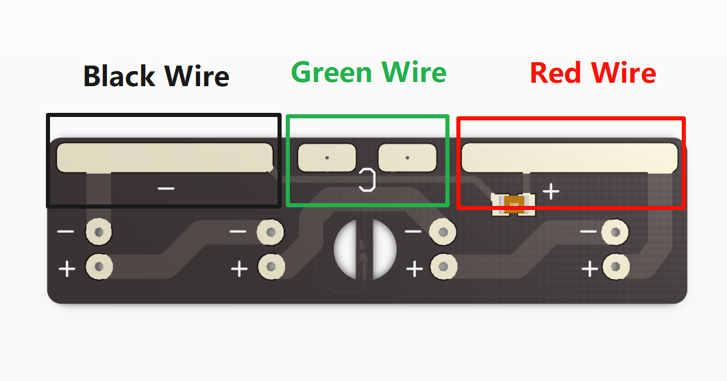
The red line is the positive pole of the laser diode, the black line is the negative pole of the laser diode, and the green line is the temperature sensor line (positive and negative poles are not distinguished).
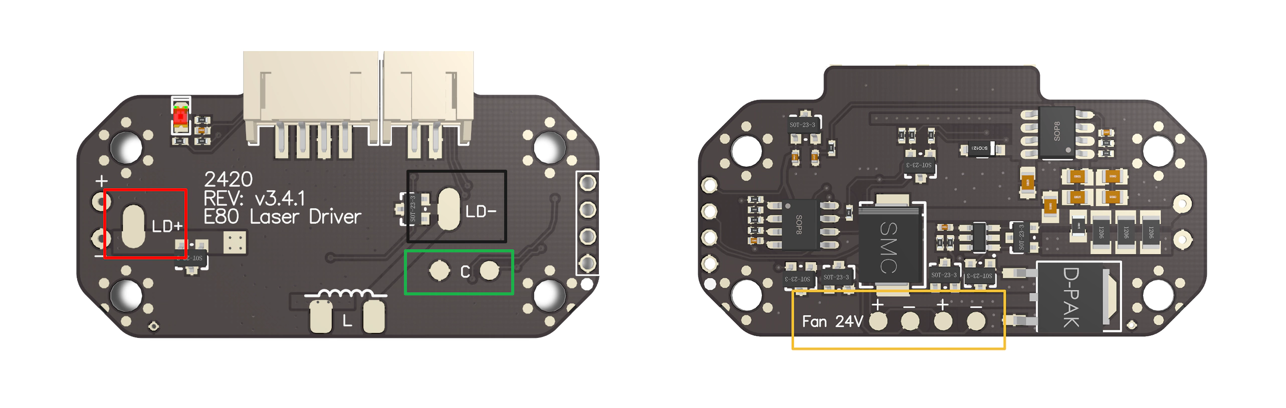
¶ Main driver board
Below is a picture of the driver board (version v3.3.2)

Below is a picture of the driver board (version v3.3.3 or above versions use a similar structure, the difference from v3.3.2 is that the fan welding position is on the reverse side).
¶ How to wire
The pad in the red frame of the small board should be connected to the pad in the red frame of the main driver board using a red wire.
The pad in the black frame of the small board should be connected to the pad in the black frame of the main driver board using a black wire.
The pad in the green frame is the temperature measurement line. The pad in the green frame of the small board should be connected to the pad in the green frame of the main driver board. The polarity is not distinguished. Any one-to-one connection is OK.
The yellow frame is the fan power line. E80 has two cooling fans. The two cooling fans are connected in parallel. Please pay attention to the positive and negative polarity of the fan.
¶ FAQ
¶ My temperature sensor is black and is not connected to the pad inside the green frame of the small board
Your laser module uses a new version of the temperature sensor. You only need to connect the two leads of the black sensor to the two pads inside the green frame of the main driver board. There is no need to distinguish the positive and negative polarity.