¶ Connect the wires correctly
The following figure shows the wiring diagram of the NEJE 3 control board. The NEJE 5 control board is similar to this one (without the limit switch).
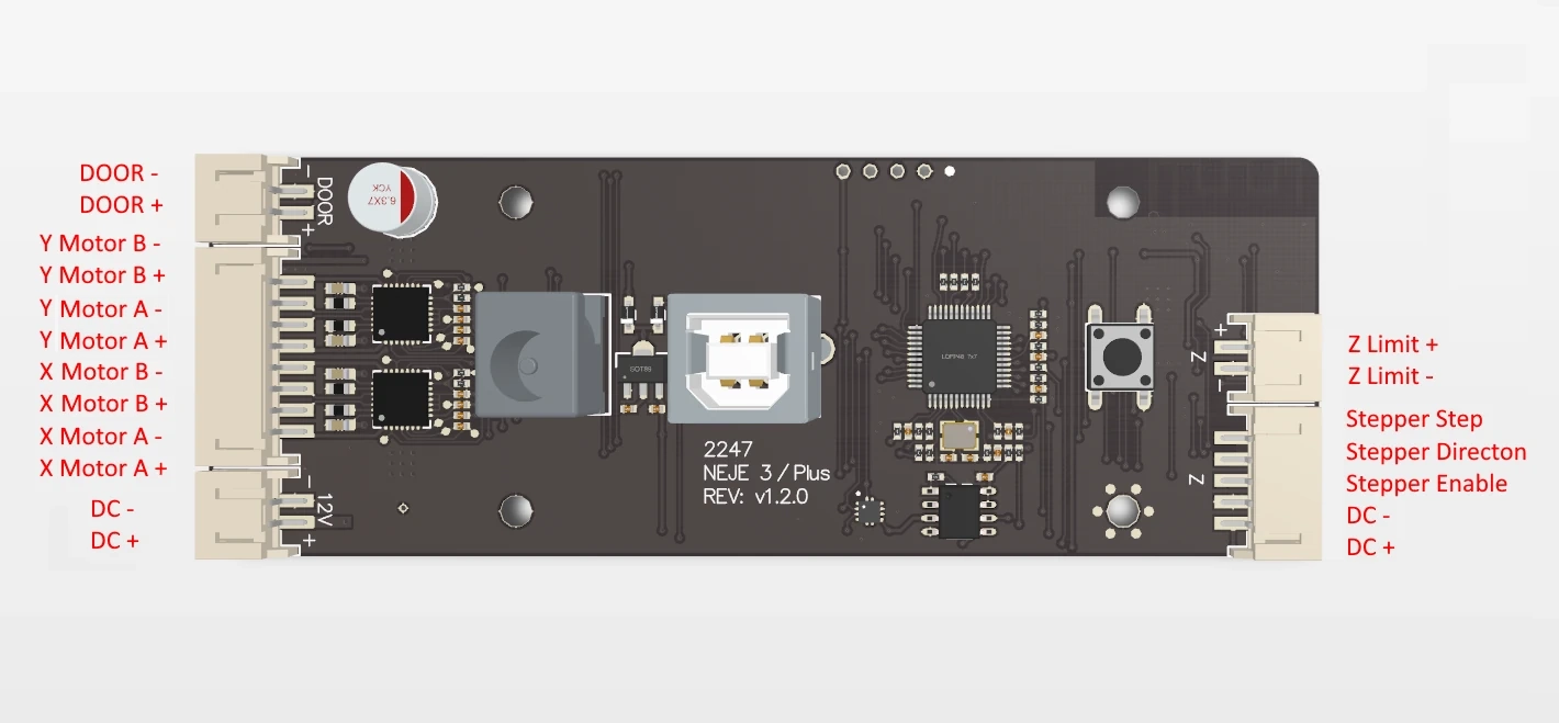
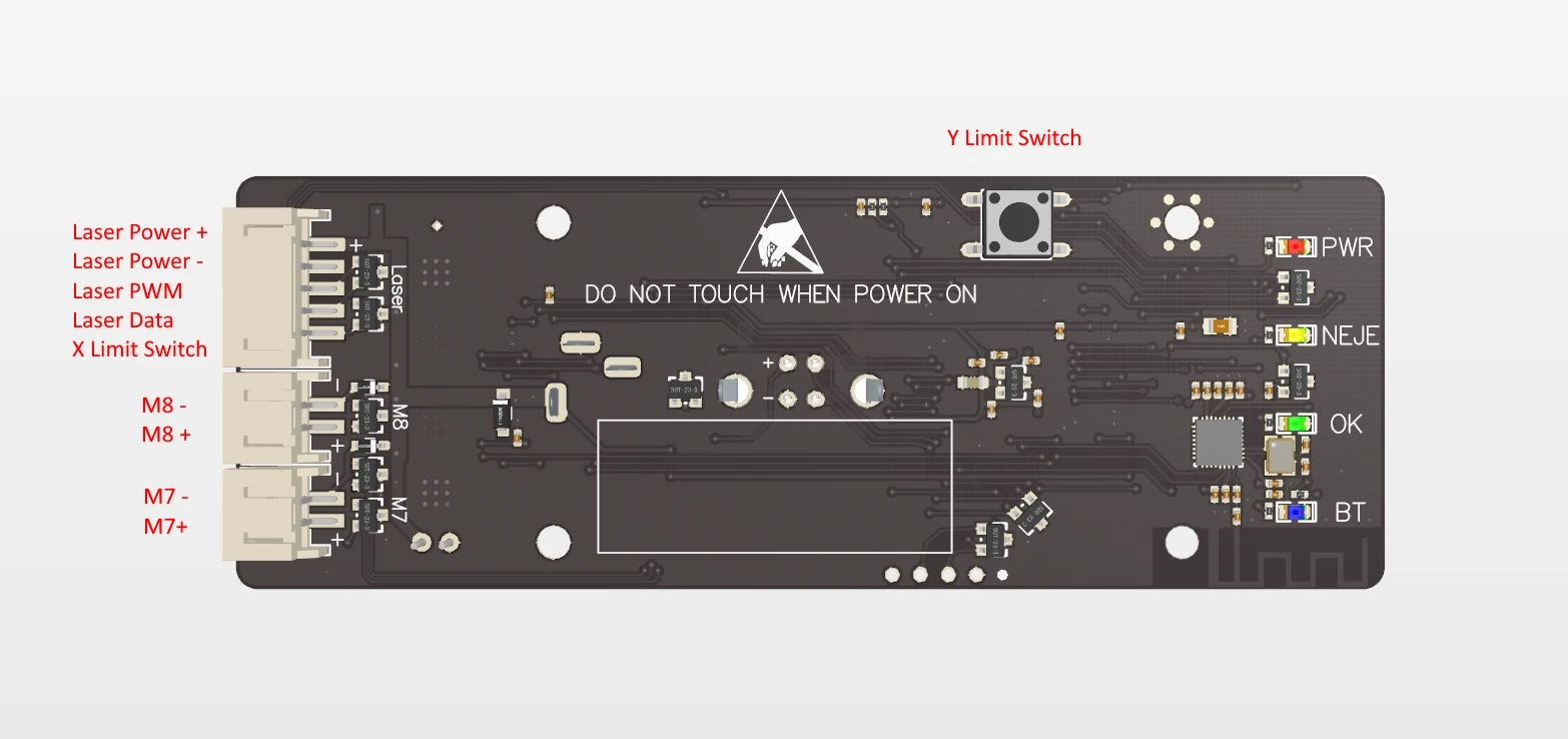
The following figure is the wiring diagram of the NEJE Max control board (version lower than v2.0.0)
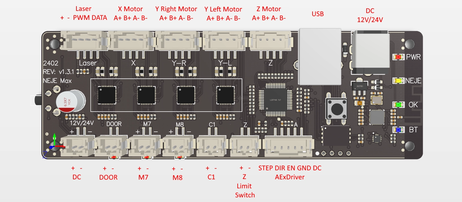
The following figure is the wiring diagram of the NEJE Max control board (version higher than or equal to v2.0.0)
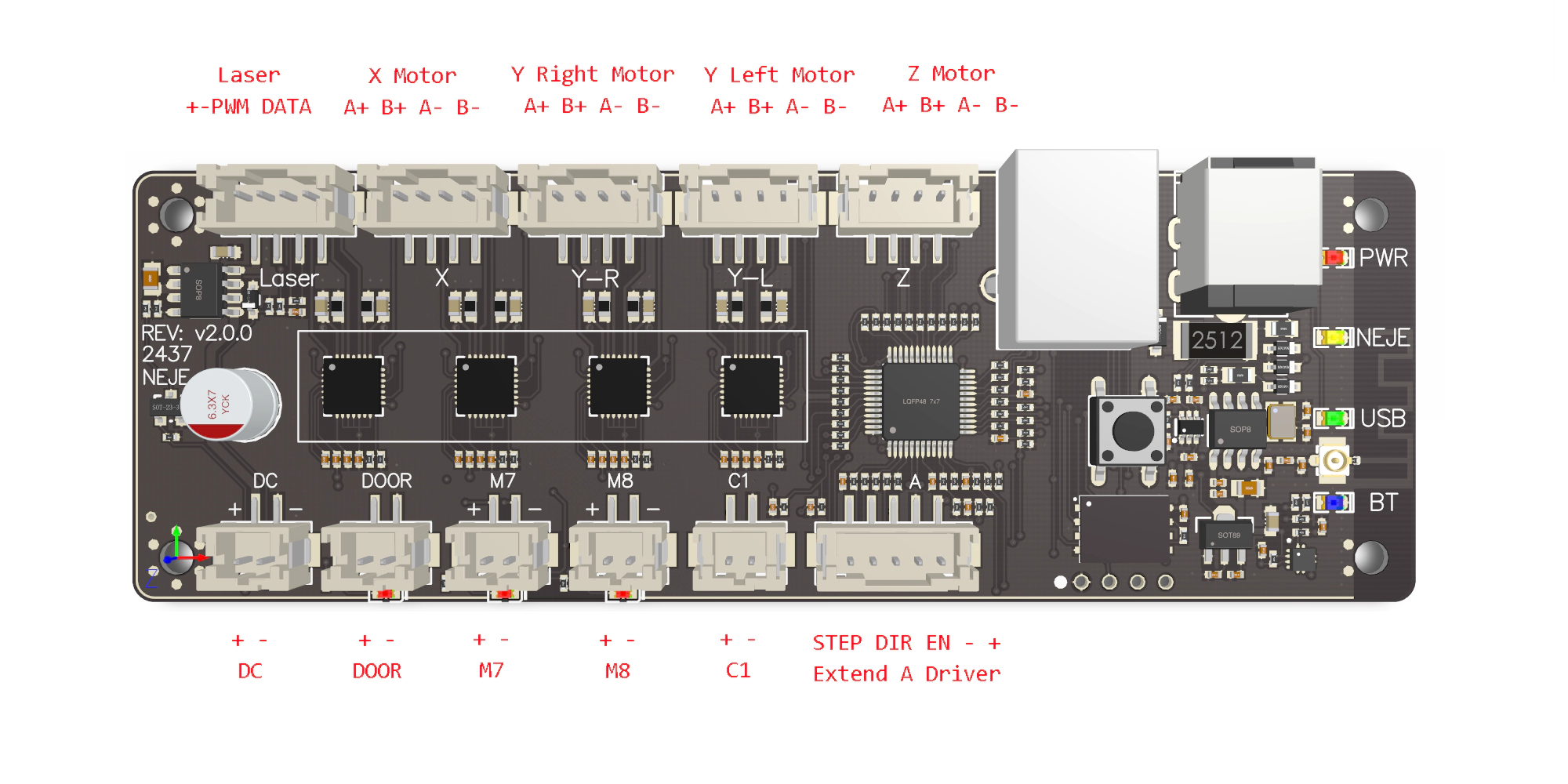
Compared with the old motherboard, the Z-axis limit switch interface has been removed because it is no longer needed. If your device has a Z-axis limit switch wiring (connected to the 2P line of the Z axis), please do not connect it to the motherboard and keep it floating.
Looking for wiring diagrams for the NEJE Max 2S and NEJE Max 3? Please Click this link
¶ Connect the wires reliable
Please make sure the connector and cable are fully connected.
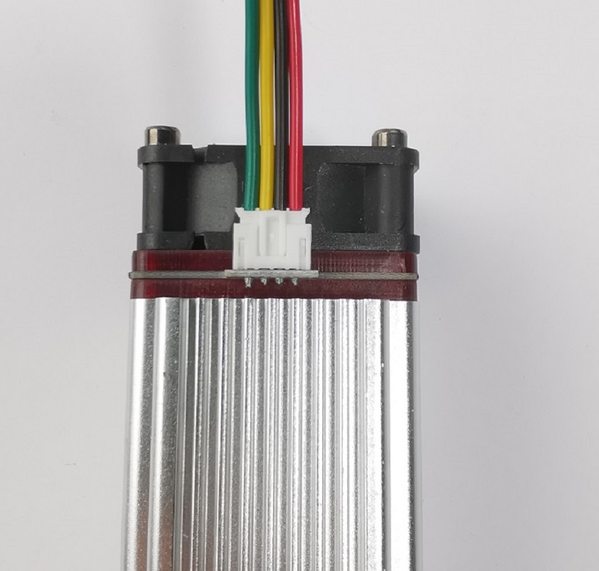
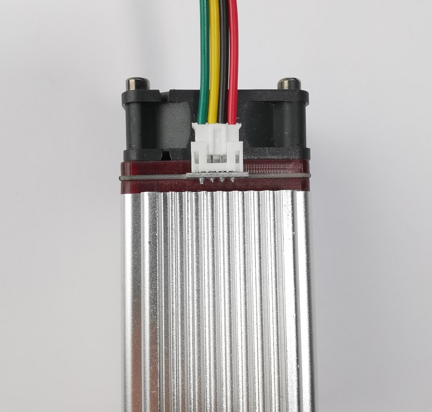
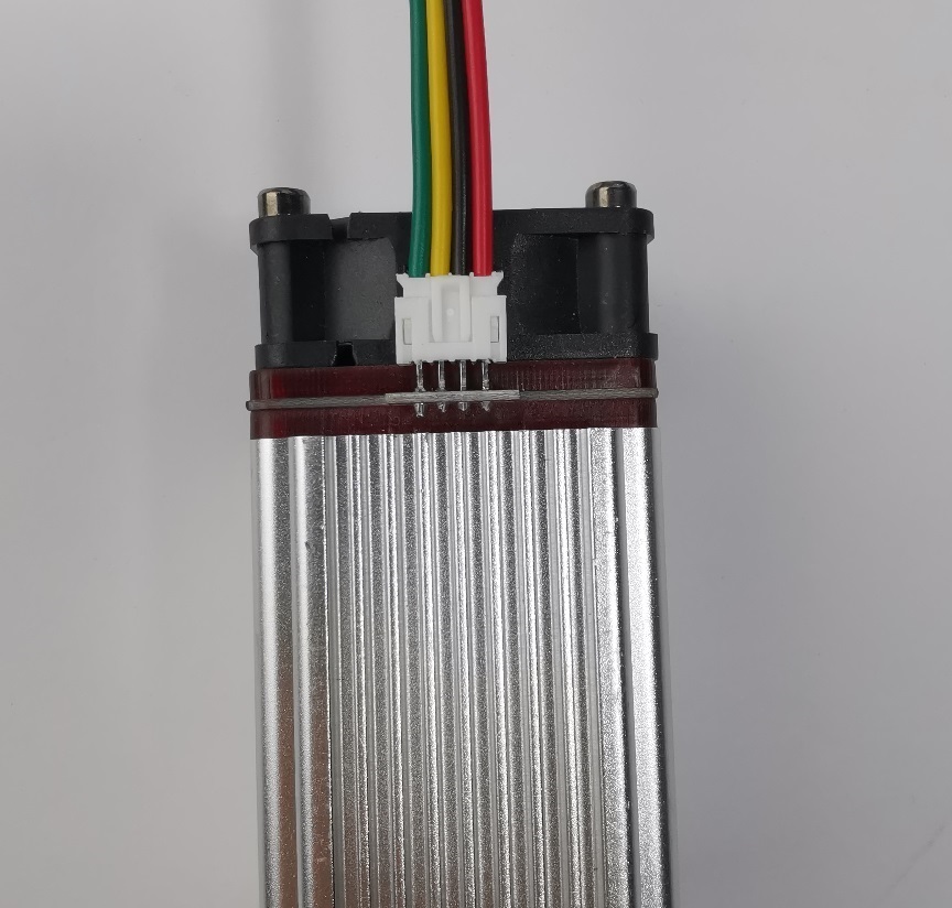
Good
Not fully connected
Connector damage


Good
Not fully connected


Good
Not fully connected


Good
Damaged cables


Good
Damaged connector