¶ Introduction
We have released two versions of the 40 series laser modules, a new model and an older model.
Here's how to determine if your laser module is the new or older model:
Remove the four screws on top of the laser driver; the cooling fan will then detach from the laser module body.
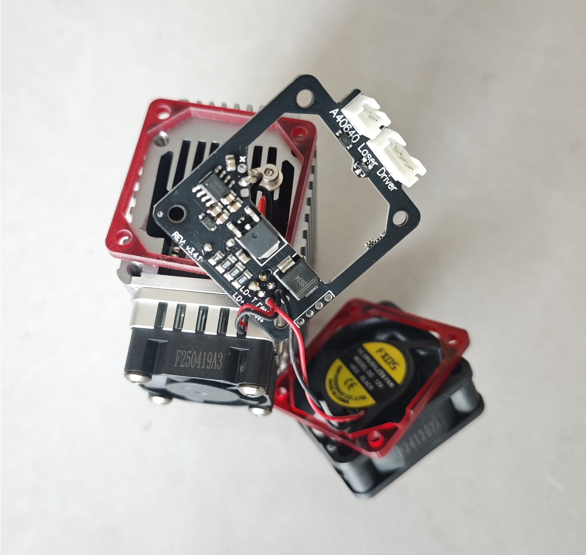
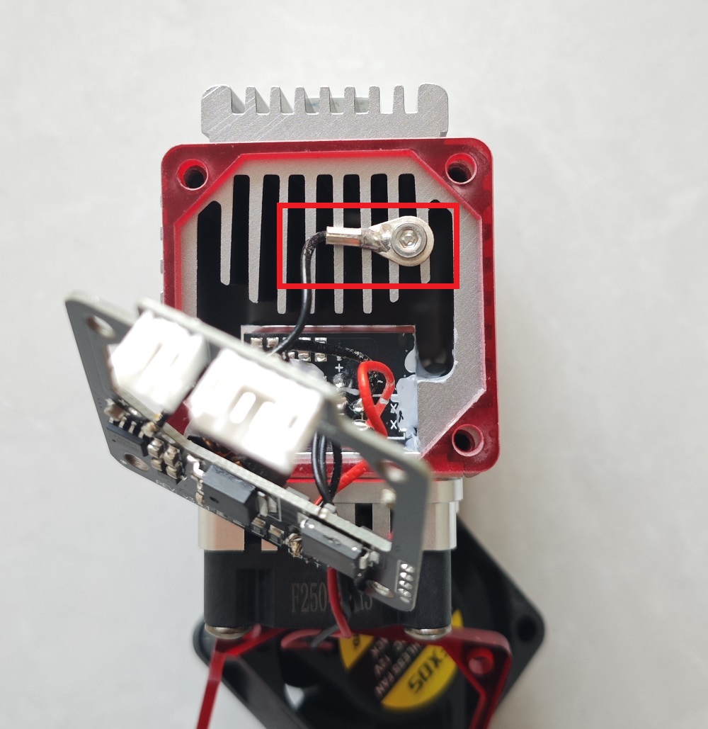
If the laser driver board is connected to the laser module body using a wired connection, your laser module is the new model, as shown in the image below:
If the laser driver board is hard-connected to the laser driver body, your laser module is the older model, as shown in the image below:
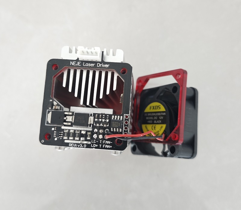
Note: The laser driver board of the older model laser driver is not movable. Do not forcefully pry the driver board, as this may damage the connector.
¶ Replacing the Laser Driver Board
Before you begin, you may need to learn some basic soldering techniques. Please... Click this link
You will receive a large circuit board and a small circuit board. The large circuit board is the laser driver board. The small circuit board is the connector board (generally, this board does not need to be replaced).
Now, please replace the laser driver board according to your laser module version and your laser module repair kit version.
¶ New Laser Driver + New Repair Parts
This is relatively the simplest.
You only need to replace the old laser driver board with the new one.
Here are the detailed steps:
Disconnect the laser positive and negative terminals from the old laser driver board.
Disconnect the temperature sensor probe connection from the old laser driver board.
Disconnect the grounding wire from the old laser driver board.
Connect the laser positive and negative terminals to the new laser driver board.
Connect the temperature sensor probe to the new laser driver board.
Connect the grounding wire to the new laser driver board.
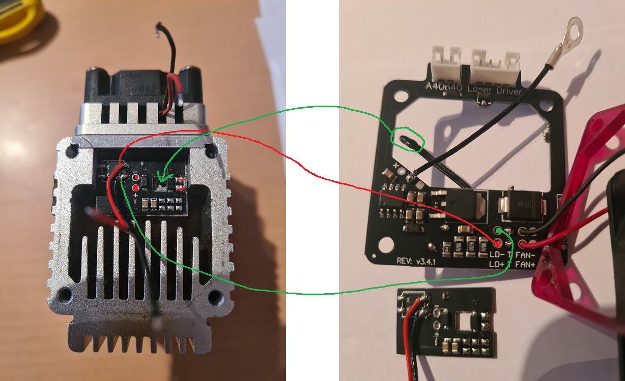
Here is a connection diagram.
Note: You may not need to use the new temperature sensor probe; the old temperature sensor probe can be used with the new laser driver board.
¶ Old Laser Driver + New Repair Parts
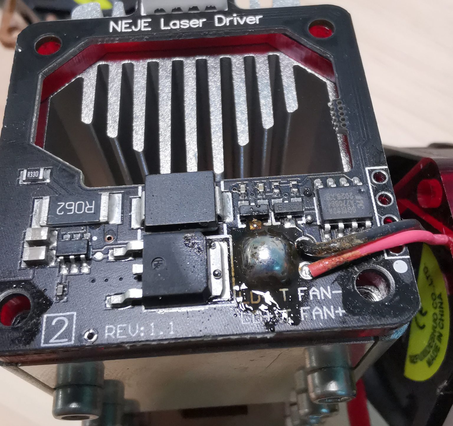
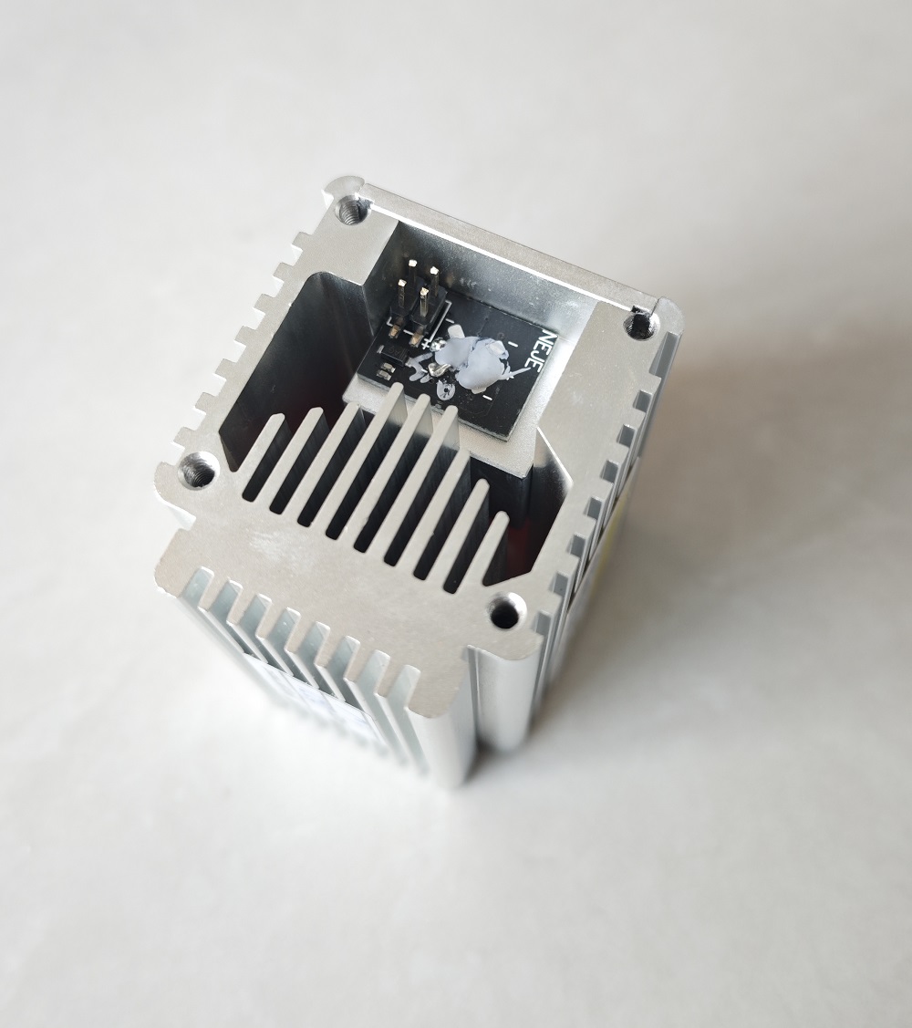
Heat these 4 solder points simultaneously and remove the driver board.
 =800x)
Use scissors or pliers to cut off the pins of this header.
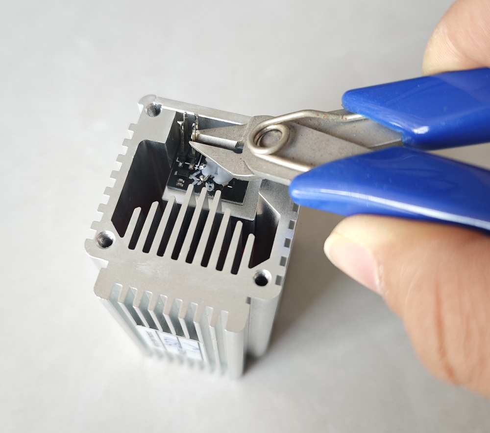
You will get
Note: Pulling the header forcefully may damage the PCB.
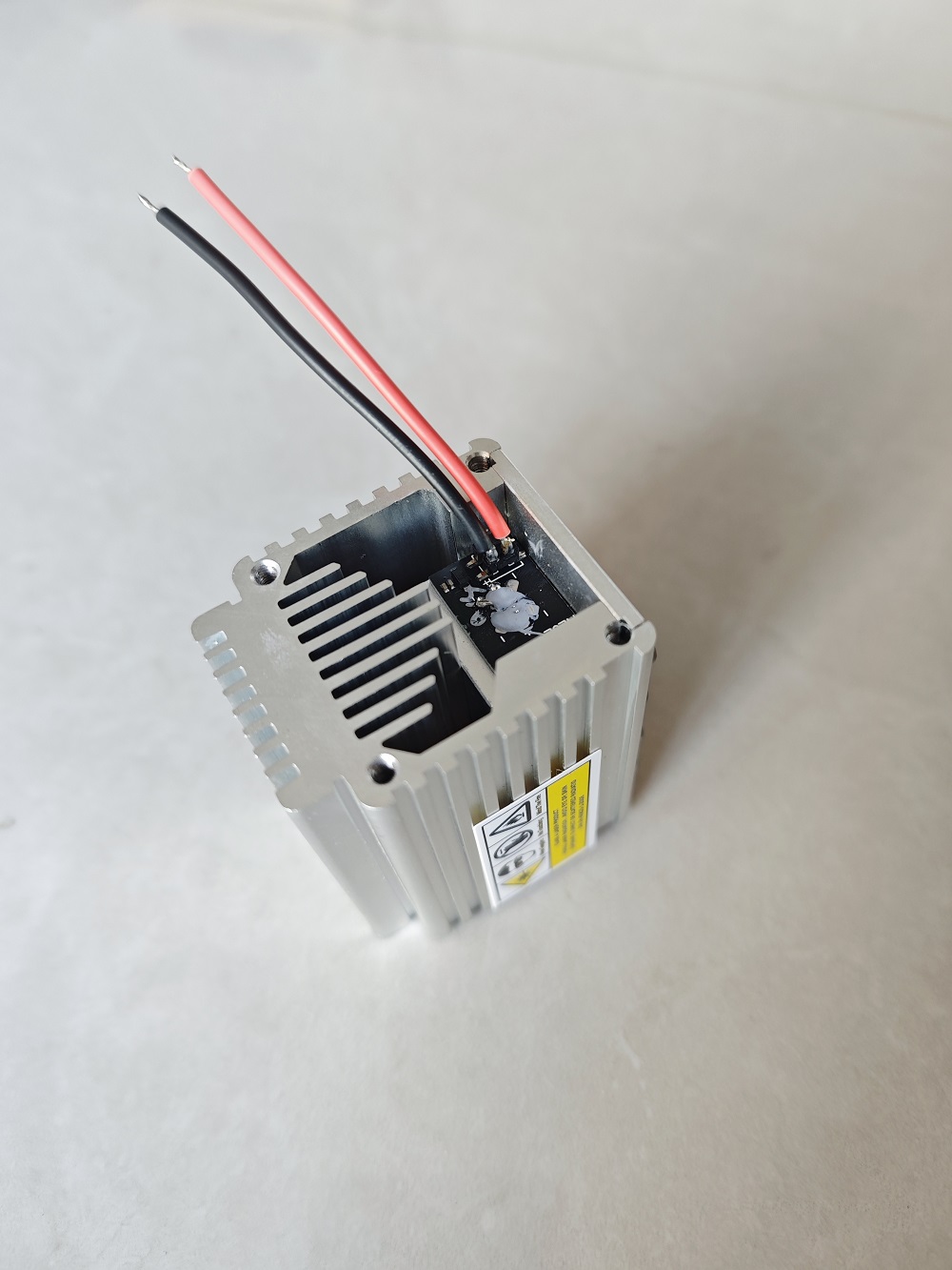
Solder the positive and negative terminals here.
Place the temperature sensor probe here (preferably secured with silicone rubber).
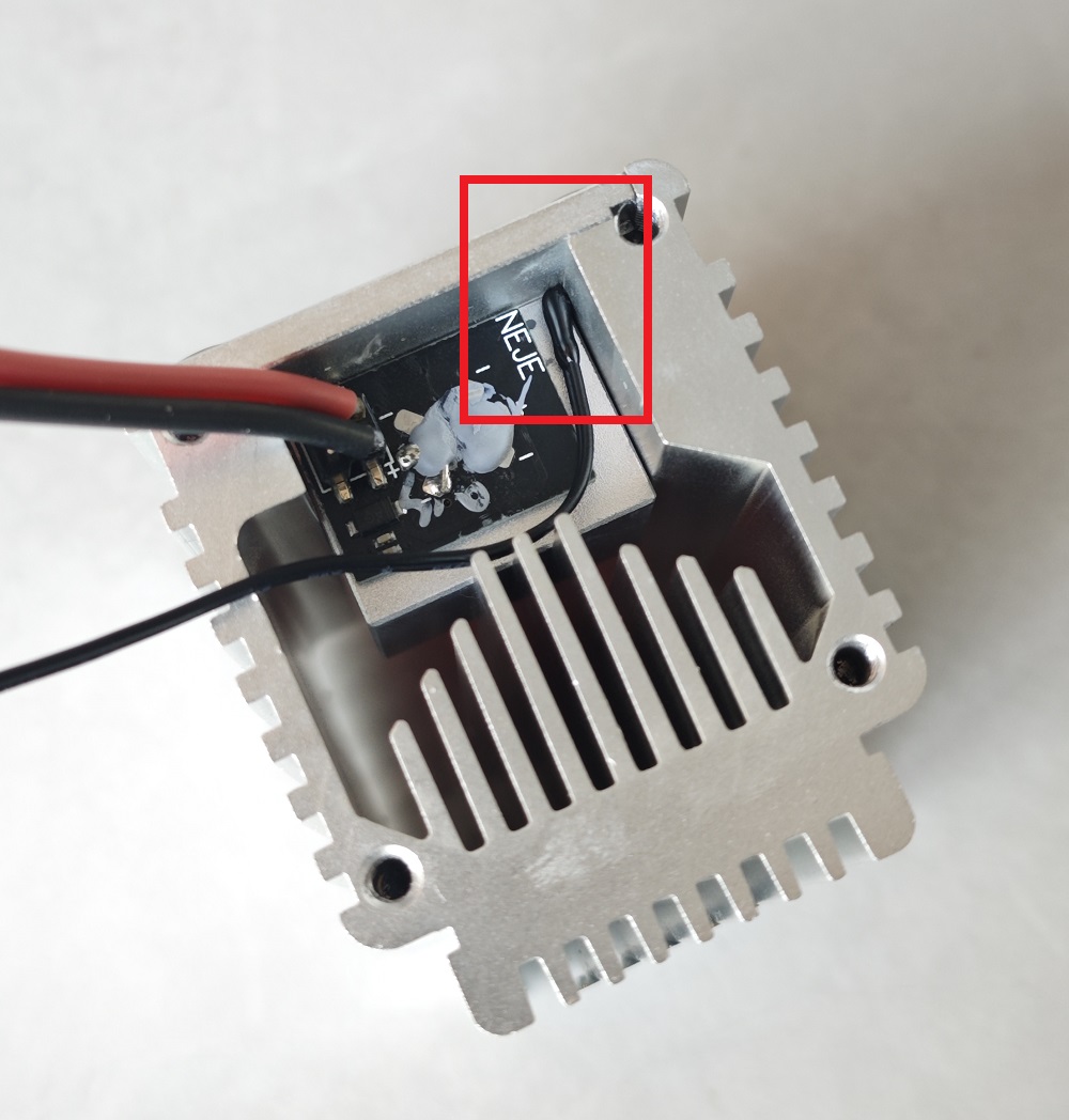 =800x) If you can't find a place to put the temperature probe, just keep the probe close to the top of the laser core (using 704 silicone rubber for fixing is best). The temperature sensor has no positive or negative polarity.
Connect the laser positive and negative wires to the new driver board. Below is a diagram showing the soldering of the positive and negative wires.
Secure the ground wire here.
¶ Old Laser Driver + Old Repair Parts
Please click this link for details.